



Speed Sensors for Axle Measurement and Recalibration
A speed reading can be inaccurate even when the sensor is working. Speed sensors measure rotation at a wheel, axle or gearbox and send an electrical signal for processing. To recalibrate vehicle speed, an ECU can be driven at a known speed and set to that reading.
It’s easy to assume a mismatched reading means a faulty sensor, but the sensing method, target and installation all affect the signal. This guide explains how Hall-effect, inductive, magnetoresistive and optical sensors detect rotation, and how axle readings can be recalibrated. It also covers practical checks for diagnosing a signal problem, helping you understand where an inaccurate reading may originate and what to investigate next.
Key Takeaways
- Match the sensing method to the target: Hall-effect systems read magnetic targets, whilst inductive, magnetoresistive and optical designs detect rotation in different ways.
- For a Hall-effect setup, assess the target wheel’s teeth and the sensor-to-wheel air gap, as both affect signal detection.
- Compare driven and undriven wheel readings to help identify wheel slip and understand how the vehicle’s speed signal is being calculated.
- Recalibration can involve driving at a known speed and setting the ECU to that reading; the signal path and target measurement matter too.
- Use the sensor’s output behaviour and the vehicle system it supports to narrow down whether a reading issue points to the sensor, its installation or the wider setup.
Geartooth sensing with Hall-effect sensors
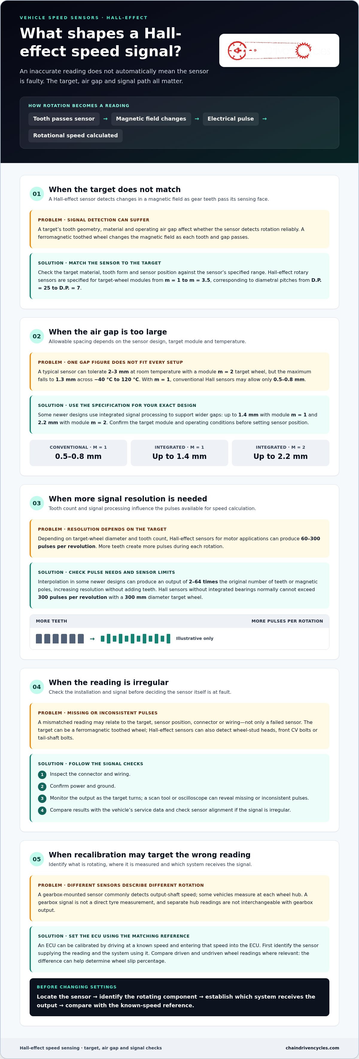
A Hall-effect sensor detects changes in a magnetic field as gear teeth pass its sensing face. To select the right sensor, match it to the target wheel’s tooth geometry, material and operating air gap.
Geartooth Signal Detection
A ferromagnetic toothed wheel changes the magnetic field at the Hall sensor as each tooth and gap passes. The sensor converts those changes into electrical pulses that can represent rotational speed. Depending on the target wheel’s diameter and tooth count, Hall-effect sensors for motor applications can produce 60 to 300 pulses per revolution. More teeth create more pulses during each rotation.
Air gap is a key selection factor. A typical sensor can tolerate 2 to 3 mm at room temperature with a module m = 2 target wheel, but the maximum falls to 1.3 mm across −40 °C to 120 °C. With module m = 1, conventional Hall sensors may allow only 0.5 to 0.8 mm.
Hall-Effect Rotary Measurement
Hall-effect rotary speed sensors read a ferromagnetic target wheel as it turns, then provide pulses for calculating rotational speed. Specified target-wheel modules range from m = 1 to m = 3.5, corresponding to diametral pitches from D.P.=25 to D.P.=7. Check that the wheel’s tooth form and sensor position suit the sensor’s stated range.
Some newer designs use integrated signal processing to work across larger gaps: up to 1.4 mm with module m = 1 and 2.2 mm with module m = 2. Interpolation can produce an output of 2-64 times the original number of teeth or magnetic poles. That can increase signal resolution without adding teeth to the target.
Hall Sensor Types
For this comparison, distinguish conventional Hall sensors from designs with integrated signal processing. A conventional sensor’s usable gap depends on the target module, while signal processing can support wider gaps. Hall sensors without integrated bearings normally cannot exceed 300 pulses per revolution with a 300 mm diameter target wheel. Confirm the target size and required pulse count before choosing.
To choose a vehicle speed sensor, match its connector and signal requirements to the vehicle’s system. Then check the target material, tooth geometry and mounting gap. For a transmission-mounted sensor, confirm it reads the intended rotating component.
There is no single fitting-inclusive price for Ireland that applies to every vehicle. The total depends on the sensor specification, access to its mounting position and the diagnostic work needed to identify the fault.
To test a Hall sensor, inspect the connector and wiring, confirm power and ground, then monitor its output as the target turns. A scan tool or oscilloscope can reveal missing or inconsistent pulses. Compare the results with the vehicle’s service data, and check sensor alignment if the signal is irregular.
A gearbox-mounted Hall-effect or interrupt-style sensor can share its factory signal with an ECU digital input.
A Hall-effect sensor can detect wheel-stud heads, front CV bolts or tail-shaft bolts.
Axle speed measurement and recalibration
An axle reading is created by measuring rotation and converting it into an electronic signal. Speed sensors may measure at a gearbox or wheel hub, so identify the measurement point before interpreting the reading. A factory vehicle speed sensor is commonly mounted on the gearbox to detect output-shaft speed; some vehicles measure each wheel hub.
These readings serve different purposes. A gearbox signal can provide vehicle-speed information to the engine management system, while individual wheel readings let control systems compare wheel behaviour. The measured component and the ECU receiving the signal determine what the reading represents. For example, an output-shaft reading describes gearbox rotation, not a direct measurement at each tyre.
How axle readings are measured
As a shaft or wheel rotates, the sensor produces a signal linked to that movement. The vehicle’s electronic system processes the signal to calculate speed. A gearbox-mounted sensor measures the output shaft, not the road directly; the ECU interprets that rotational information as vehicle speed.
Wheel-level readings allow another comparison. Measuring a driven wheel alongside an undriven wheel can help determine the slip percentage between them. Traction control can use the difference to assess whether the driven wheel is turning at a different rate from the other wheels. This is distinct from simply reading gearbox output.
Recalibrating the ECU
An ECU can be calibrated for vehicle speed by driving at a known speed and entering that speed into the ECU. This gives the system a reference for interpreting the sensor signal. The calibration input should match the reading being adjusted. Avoid changing a sensor signal without understanding how the ECU processes it.
Before recalibrating, identify which sensor supplies the reading and which system uses it. If the signal comes from a gearbox output shaft, establish whether the ECU uses that input. If the vehicle measures wheel hubs, compare the relevant wheel readings instead. This helps distinguish a calibration mismatch from a problem with measured rotation.
Practical checks before changing settings
Follow the signal path in order: locate the sensor, identify the rotating component it measures, and establish which electronic system receives its output. Compare the displayed speed with the known-speed reference used for calibration. If wheel readings differ, consider whether the comparison is between driven and undriven wheels, since their rotational behaviour can vary under traction.
A gearbox signal and separate hub readings are not interchangeable: they describe rotation at different points in the vehicle. Record which input is being used to make recalibration more precise and avoid adjusting the wrong reading. This also clarifies whether speed sensors measure the component relevant to the displayed value.
For cyclists comparing electronic ride information, keep vehicle axle readings distinct from bicycle equipment. An electric hybrid bike is a separate cycling option, not a substitute for vehicle axle measurement or ECU recalibration. That distinction helps keep a cycling purchase decision separate from vehicle diagnosis.
Inductive speed sensors
Inductive sensors detect rotation through changes in a magnetic field and are commonly used for wheel and transmission measurements. Their output depends on the passing target and operating conditions, so match the sensor type to the system it must serve.
How inductive detection works
A variable-reluctance sensor generates an electrical signal as a ferromagnetic target moves past its sensing element. The changing magnetic field produces a waveform that an electronic control unit can interpret as rotational speed. Variable-reluctance speed sensors are listed for operation above 10 kHz, a useful specification when comparing a sensor with the system’s signal requirements.
Unlike a sensor that needs a separate power supply to generate its signal, a variable-reluctance unit relies on movement of the target. Its signal changes as the target’s teeth pass, so a damaged tooth, incorrect alignment or wiring fault can affect the output. Diagnosis should cover the complete path from target to control unit.
Vehicle applications and signal sharing
Wheel readings support safety systems such as anti-lock braking systems (ABS), traction control and electronic stability control. ABS wheel sensors help an ABS system monitor wheel behaviour during braking. Identify the signal correctly during diagnosis rather than treating every wheel-speed fault as an isolated sensor issue.
Sharing a magnetic inductive ABS signal with an aftermarket ECU may require electrical circuits to isolate the aftermarket ECU from the ABS computer. This matters because the signal serves an existing vehicle system as well as the additional input. For a gearbox application, identify the intended input, output or internal measurement before choosing a sensor.
Some automatic transmission systems use three sensors to measure input speed, output speed and another internal speed. A listed 12 V speed and RPM sensor has three contacts, whilst a listed wheel sensor operates from −40 °C to 150 °C. These specifications illustrate why connector, supply and temperature requirements belong in the selection process.
Testing and specialised examples
Begin diagnosis by inspecting the target, sensor mounting and wiring, then measure the output as the target rotates. Compare the waveform with the vehicle’s service information. A weak or absent signal may point to the sensor, wiring or target. The Federal Highway Administration describes inductive-loop traffic sensors arranged as a speed trap, with two sensors placed close together along a vehicle’s path.
Rail applications add other signal-monitoring details. Two-wire wheel-slide protection sensors can use current outputs of 7 mA and 14 mA to detect broken cables. Some provide around 7 V when signal frequency falls below 1 Hz, giving the monitoring system a distinct condition to detect.
Vehicle safety systems, including ABS, traction control and electronic stability control, use wheel-speed sensor signals. Keep this shared role in view when assessing a wheel-speed signal alongside the underlying rotational measurement.
Magnetoresistive sensors
Magnetoresistive sensors read changes in a magnetic field as a target rotates, producing signals that an electronic system can use to assess speed. Their documented air gap can reach 4.0 mm, making target clearance an important selection factor alongside wheel geometry and signal requirements.
How magnetoresistive sensing works
A magnetoresistive element changes its electrical resistance in response to a magnetic field. As a magnetic or ferromagnetic target moves past, the sensor converts field changes into electrical signals. The vehicle’s electronics interpret those signals to establish rotation and, where supported, direction.
The stated 4.0 mm maximum air gap is a useful comparison point, not a universal installation setting. The actual working gap depends on the sensor and target combination. Check the required clearance against the target wheel’s position, mounting arrangement and operating conditions before selecting a unit.
Multichannel signals and encoder resolution
A multichannel magnetoresistive encoder example scans a target wheel with 256 teeth and generates sine and cosine signals. These two waveforms provide information about the target’s changing position, rather than simply marking each tooth with a single pulse. The design can therefore support detailed rotational measurement when its encoder and processing electronics are compatible.
For selection, match the encoder output to the receiving system. A controller designed to process sine and cosine signals needs the relevant inputs and signal handling. A system expecting a different output may not interpret the encoder correctly, even if the target wheel has 256 teeth. Confirm the required signal type and target format together.
Direction sensing and vehicle functions
Wheel sensors can detect direction as well as speed. Direction information can support functions such as hill start assist and park assistance, where forward or reverse movement matters. A magnetoresistive sensor can suit these applications when the system can interpret its output and the target arrangement provides the necessary directional information.
This capability changes what to assess during diagnosis. If a system uses direction, check whether its signals indicate both rotation and direction, rather than considering speed alone. For example, a wheel reading that registers rotation but reports the wrong direction may affect a function differently from a missing speed signal.
Choosing and checking a sensor
Active engine speed sensors can also provide camshaft and crankshaft position by reading a ferromagnetic or magnetic encoder wheel. Target compatibility is therefore central to sensor choice. Identify the component being measured, the encoder material and the signal format expected by the engine electronics.
- Compare the required air gap with the sensor’s specified operating range.
- Match the target wheel’s magnetic properties and geometry to the sensor.
- Confirm whether the system needs speed, direction or position signals.
- Check that the receiving electronics can process the sensor’s output.
These checks distinguish a suitable magnetoresistive sensor from one that merely fits the mounting position. A 256-tooth encoder, 4.0 mm gap and sine-and-cosine output each describe a different part of the fit, so assess them as a complete system.
Optical speed sensors
Optical sensors detect rotation by monitoring changes in the light reaching a receiver. A light source illuminates a rotating target, and features such as slots or marked sections interrupt or alter the beam. Each change creates an electrical signal that a controller can interpret as movement. The right fit depends on the target, mounting arrangement and signal input required by the system.
How optical detection works
An optical assembly typically pairs an emitter with a light-sensitive receiver. As a slotted disc rotates between them, each opening lets light reach the receiver and each solid section blocks it. The resulting signal pattern represents rotation. A reflective arrangement works differently: marks on the target change how much light returns to the receiver.
Optical speed sensors are listed with speeds above 100 kHz. This is a technology specification, not a promise that every installation will operate at that rate. The target pattern, sensor alignment and receiving electronics all affect how the signal is produced and read.
What to assess before choosing
First identify the target the sensor will read. A slotted encoder disc suits a through-beam arrangement, while a marked surface may suit reflective detection. Then establish how the target sits relative to the emitter and receiver. A bracket that allows movement or misalignment can change the light received and disrupt the output.
Next, match the output to the control system. Check whether it expects pulses or another signal format, and whether it can process the sensor’s required operating frequency. For example, a controller intended for a slower input may not make useful measurements from a signal above 100 kHz. The system specification and target design should be considered together.
Installation and diagnosis
Follow a practical sequence during installation. Secure the sensor and target, align the optical path, then rotate the target and observe the output. A regular series of changes suggests the receiver is detecting the target pattern. A missing or uneven signal points to alignment, contamination, damaged markings or wiring.
During diagnosis, distinguish a light-detection issue from an electronic processing issue. First inspect the emitter, receiver and target surface. Then check the output at the sensor and where it enters the controller. If the sensor output changes as the target rotates but the controller shows no corresponding reading, investigate the signal connection and input compatibility.
Optical sensing is most relevant when the target and installation can maintain a clear, stable light path. A slotted disc is a straightforward example, while dust or movement can obstruct detection. Choose an optical arrangement only after checking the target, mounting position and receiving system as one measurement setup.
Chain Driven Cycles: Bottecchia bicycles
Chain Driven Cycles can help if this guide has you considering a bicycle rather than a vehicle sensor. Its Bottecchia bicycles offer a practical option for riders choosing a bike, while bicycle repair services can help when an existing cycle needs attention.
For ride data and training, Assioma Power Meter Pedals provide a cycling-focused alternative to vehicle axle measurement. Electric Hybrid Bikes may suit a different kind of riding for everyday transport. These are bicycle choices, not substitutes for diagnosing or recalibrating a vehicle’s electronic system.
Contact Chain Driven Cycles to discuss a bicycle or repair service that fits your needs.
Choose the right next step for your setup
Before changing a component or calibration, decide whether your priority is resolving a vehicle reading or improving cycling data. This keeps automotive diagnosis separate from equipment chosen for a bicycle. For vehicle faults, focus on the sensor, its target and the signal path. For ride performance, choose equipment designed for cycling measurement.
Chain Driven Cycles offers Bottecchia bicycles and Assioma Power Meter Pedals. These options suit different cycling needs, from choosing a bike to measuring power during training. They are not substitutes for diagnosing a vehicle’s axle sensor or recalibrating its ECU.
If cycling equipment is your next step, explore the relevant options or contact Chain Driven Cycles to discuss your needs. With the right measurement goal in mind, you can make a more informed choice and move forward with confidence.
Frequently Asked Questions
What is a speed sensor and how does it work?
A speed sensor measures rotation and converts it into an electrical signal that a vehicle or machine’s control system can interpret. A wheel-mounted unit, for example, can provide readings used by vehicle safety systems, while a gearbox sensor can supply rotational information to engine management. The output describes movement at the measurement point; the receiving system uses that information for its intended function.
What types of speed sensors are used in vehicles and machinery?
Common types include Hall-effect, inductive, magnetoresistive and optical sensors. Hall-effect and magnetoresistive designs respond to magnetic changes, while inductive sensors generate a signal as a suitable target moves past. Optical units detect changes in light. The right type depends on the target, mounting conditions and the signal the vehicle or machine’s control system is designed to receive.